Optoma HD20 DLP Projector – Dark Spot Repair
It Could Be Caused by a Burnt Lens That is Easily Fixable
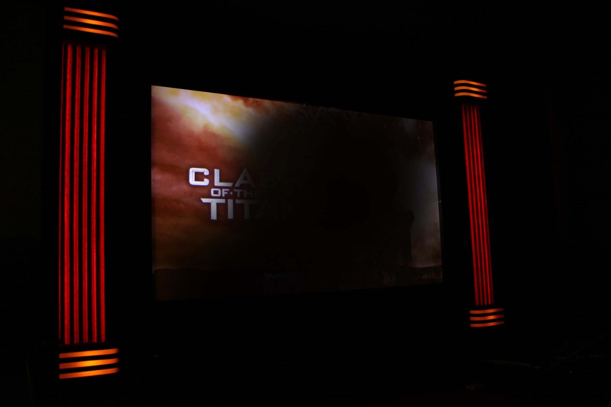
Can You Find the Dark Spot Problem In This Image?
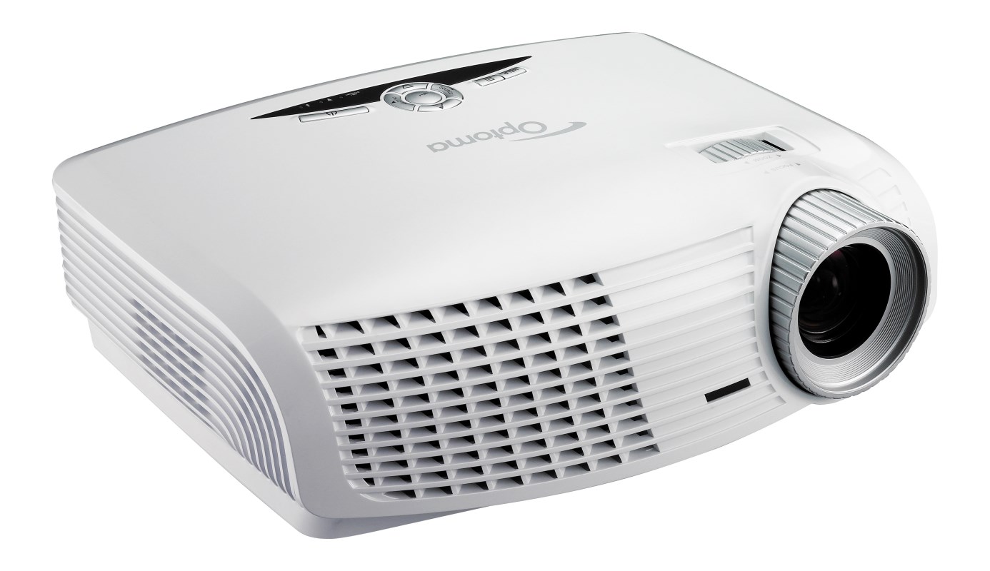
Optoma HD20 DLP Projector
The Optoma HD20 is a fairly popular DLP projector with a 1920 x 1080 native resolution and an attractive price tag. It also seems to be afflicted with an unusual tendency to suddenly develop a diffused dark area (sometimes inaccurately described as a blurry area) that may obscure part or nearly all of the projected image. This sudden darkening may also be accompanied by a strong smell of melting plastic, because as in the case described here, plastic is actually melting and charring.
I had been looking for a full HD projector to use to build a high-resolution 3D printer, and I ran across this unit suffering from the dark spot problem on Craigslist for $100. I was aware that projectors with this problem could be user-repairable, and when I looked at the unit I was able to see enough to determine that the large dark area on the right side was indeed caused by a melted inner lens.
Almost Unbelievable Meltdown of Internal Lens
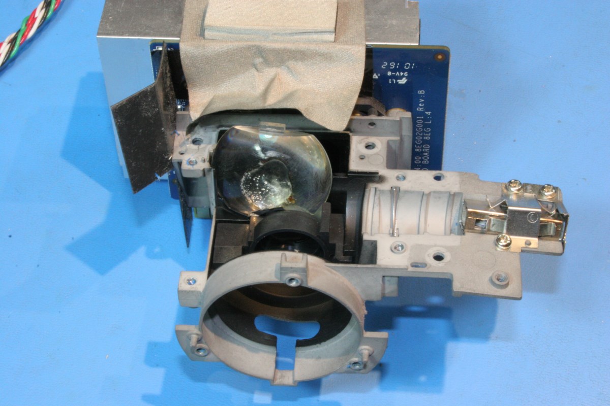
The cause of the dark region on the projected image is an oddly-shaped aspherical plastic lens that is the final element in an optical path that channels light from the reflector lamp on the left front of the unit. Light is collimated, guided horizontally under the main projection lens onto an angled mirror, and finally reflected upward through the offending plastic lens onto the face of the DMD (Digital Micromirror Device) chip. This lens is not part of the image path – the large projection lens performs that function. This one is part of the illumination path for the micro mirror chip, and as such it is tolerant of some defects. Nevertheless a lump of black coal obscuring a quarter or half of the lens area is going to do some damage to the light uniformity across the screen.
What causes this lens, a lens that is last of several elements, to go into meltdown is a bit of a mystery. The 230 watt lamp module cranks out a tremendous amount of light and with it a lot of heat. The module does contain an integral dichroic glass infrared (IR) filter to block most of the heat from reaching the more delicate optical elements downstream. But somehow sufficient energy is making it past this IR filter, through the dichroic color wheel and a light pipe, two glass lenses, and a first-surface mirror to cook the plastic lens. It could be that at IR wavelengths the transmission of the plastic is low and the absorption increases which would result in heating of the lens. Prolonged warmth could cause a thermal runaway where a slight darkening of the lens over time increases the absorption, causing the darkening process to accelerate quickly. Airborne impurities that add a dusty or filmy layer to the lens over time may add to the effect.
Some have attributed the sudden failures to the use of aftermarket lamp modules, and there are enough varieties out there that it is plausible that this may be factor. Variations in the bulbs themselves and the IR filters could explain why a few owners have reported the onset of the failure shortly after lamp replacement. That can’t be the cause in all cases however, because the projector shown here experienced the failure on its original lamp.
Whatever causes it, the lens is getting cooked in a spectacular fashion, and if this is your problem, you can fix it.
I will admit that I have no particular expertise or knowledge of DLP projectors. I performed this procedure once (actually twice if you count my intermediate epoxy repair of the cooked lens). But if you’ve never done it at all, I may be ahead of you, so read up. Please contact me if you find any errors – I was writing these steps from memory using the photos for reference.
Since this is more of a linear tutorial, I will deviate from my usual format and try to keep the thumbnails large and the text small. You can still enlarge the images for more detail.
BOILERPLATE WARNINGS: If you attempt this procedure, do so at your own risk. You will probably destroy your projector or electrocute yourself unless you have more worldly knowledge than can be gleaned from the few specific bits of information described here.
Unplug the unit before opening. Keep your fingers out of the circuit boards, particularly the lamp power supply on the left, even with the unit unplugged. Avoid touching anything near the circuit cards unless you have an anti-static mat.
Just looking at the color wheel can break it. Do not operate the projector while naked and wet. Wear a respirator, safety goggles, steel-toed boots, and your safety belt. Contains peanuts. May cause dizziness and diarrhea. See a specialist if the procedure lasts more than four hours. Do not tease or taunt Happy Fun Ball. Failure to observe these or any other precautions ever written could result in a continuum warp that may end all life on earth as we know it.
Now proceed with caution.
First of All, Is a Burnt Lens Actually Your Problem?
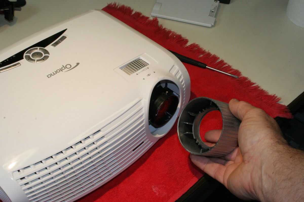
You can get a view of the problem lens very easily without even opening the case. First remove the silver bezel from the main lens by pulling it straight forward.
Next, move the zoom wheel until the pin on the lens is straight up and aligned with the little jog in the casting ahead of it.
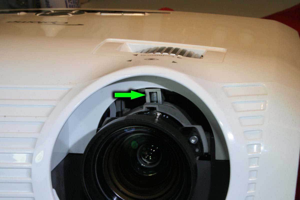
Now use a ball-end allen wrench to remove the three socket-head screws that retain the lens. This picture was taken with the light engine removed from the case, but these screws can be removed from the front.
With the screws removed, tip the lens assembly upward and then lower it to allow the zoom pin to clear the mount in front of it, and remove projection lens. You have just opened up the front of the light engine, and if your top cover was removed you would see this:
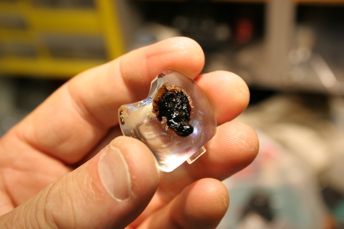
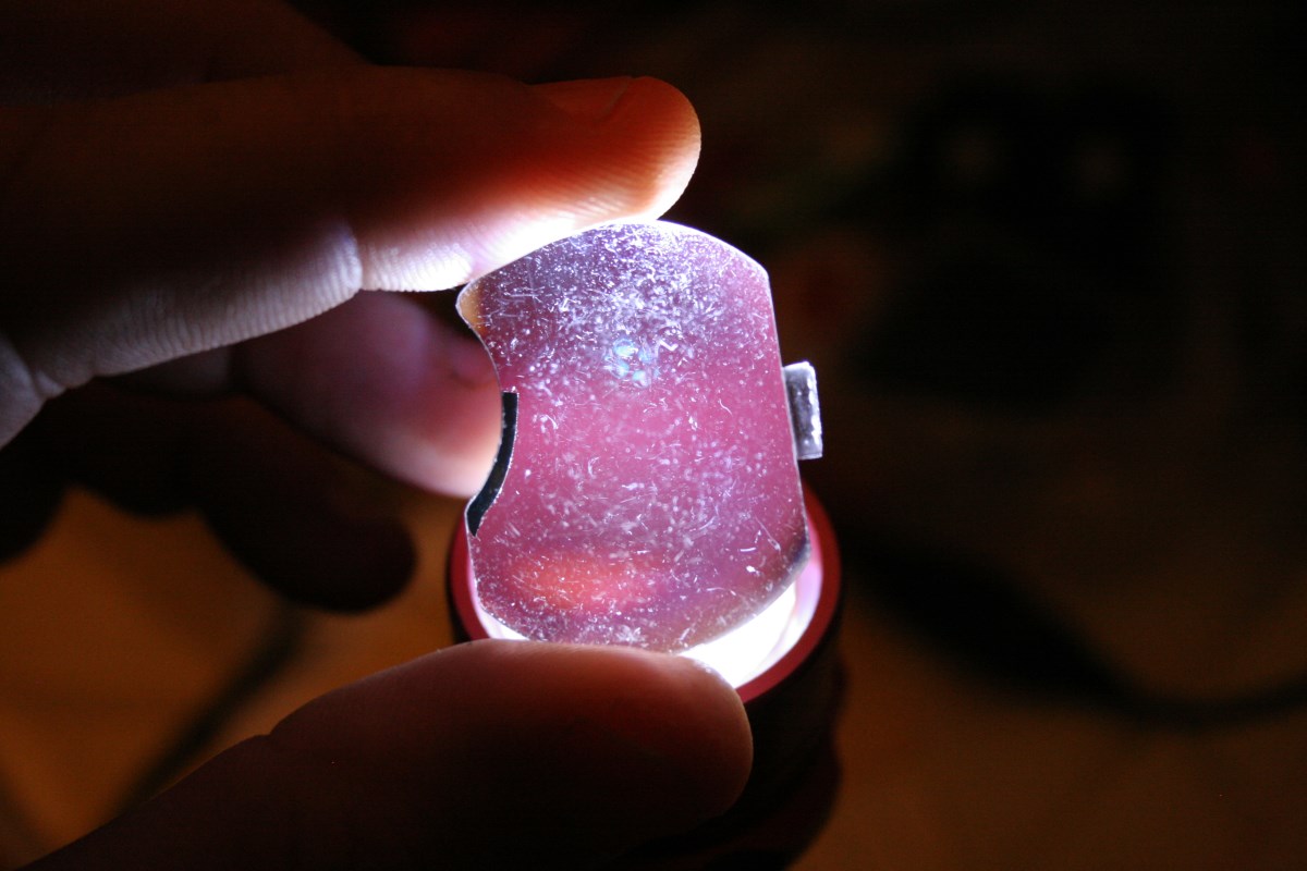
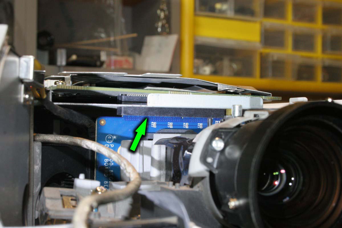
Now grab a flashlight and look inside the hole where the front lens was removed. If you see something that looks similar to the area next to the arrow below, you are on the right track.

That black blob is lava flowing out of your lens. If this is your only problem, a new lens can be purchased on eBay for $65, which is about $60 too much in my opinion. Nevertheless, if you need one, you won’t find this particular lens at a surplus store. Currently I know of two sellers on eBay that sell these for the same price – one in the US and one in China. It comes in two versions: the original plastic lens with a rectangular molding tab on the bottom and a glass lens that has no tab.
I bought my first “brand new” lens from eBay seller slp5188, and this is what I received (enlarge the image to fully enjoy what I saw):
I asked him to send a replacement, but I encouraged him to personally inspect it first to make sure it was perfect. A few days later I received this:
I was not too happy at this point but I hesitated to accept the offered refund because I needed a lens. He partially refunded $10 and relisted the lenses as refurbished and scratched for the new $55 price, so I closed the eBay case and thought I would just live with it.
A couple of days later a new listing by the same seller appeared with “brand new” lenses again offered for $65, so I was a little pissed and I decided to get into it with him again. He offered to send one of the new ones which he claimed no longer had a molding tab on the bottom.
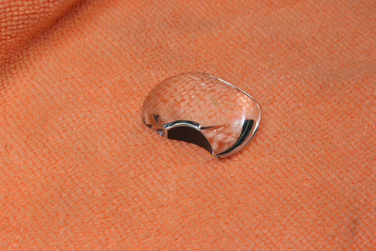
I was skeptical, thinking that the new lenses were probably someone’s recast parts of unknown pedigree. But this time I did receive a good one, and it was made of glass, not plastic. If this one melts we will truly have larger things to worry about. It appears to have an antireflective coating on it (as did the original plastic lens) and the focal length seems to be at least close to the original. Despite the steps it took to get there, I was happy enough that I ended up giving a positive feedback. The seller was cooperative throughout (even though I don’t think he knows much about what he is actually selling) and he paid for both return shipping costs. The point of this story is that if you choose to buy from this seller (the alternative seller is located in China), take steps to confirm that the lens is glass (without the tab) and that it is perfect (good luck with that). Here is the glass lens:
There is another crude, no-cost alternative to buying a new lens that will at least get your screen to light up again, but I will cover that at the end.
Replacing the Lens
TIP: when reinstalling screws in any equipment, but particularly in plastic threads, it is generally helpful to rotate the screw in reverse until you feel in click inward slightly, and then start tightening. This aids the alignment and will greatly reduce the chance of cross-threading or cutting new threads in soft material.
Let’s say you have purchased a replacement lens and you need to install it. Now you will need to open the case.
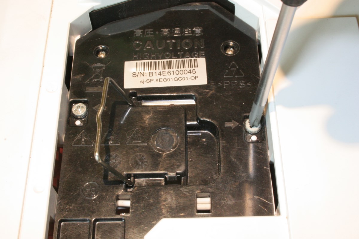
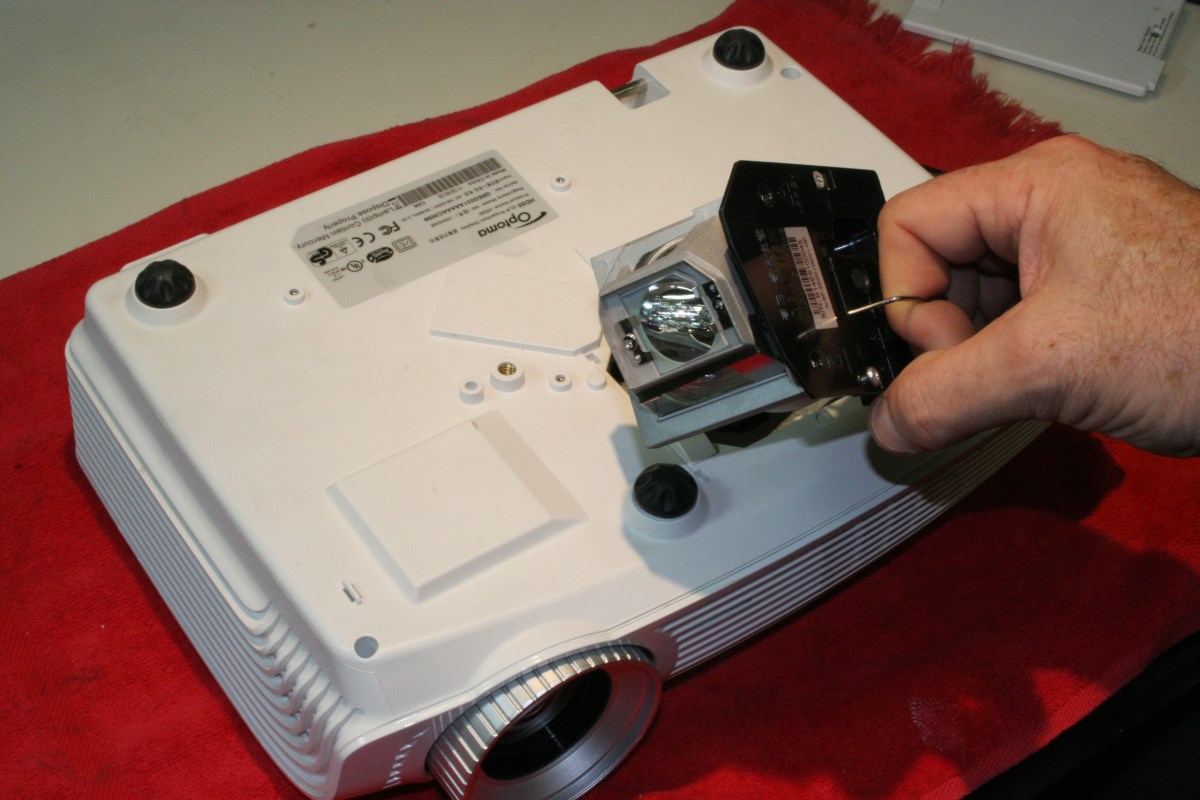
Flip the projector upside down, loosen the screws on the lamp module, and remove it. Do not touch the bulb, the reflector, or the IR filter glass. Just use the handle.
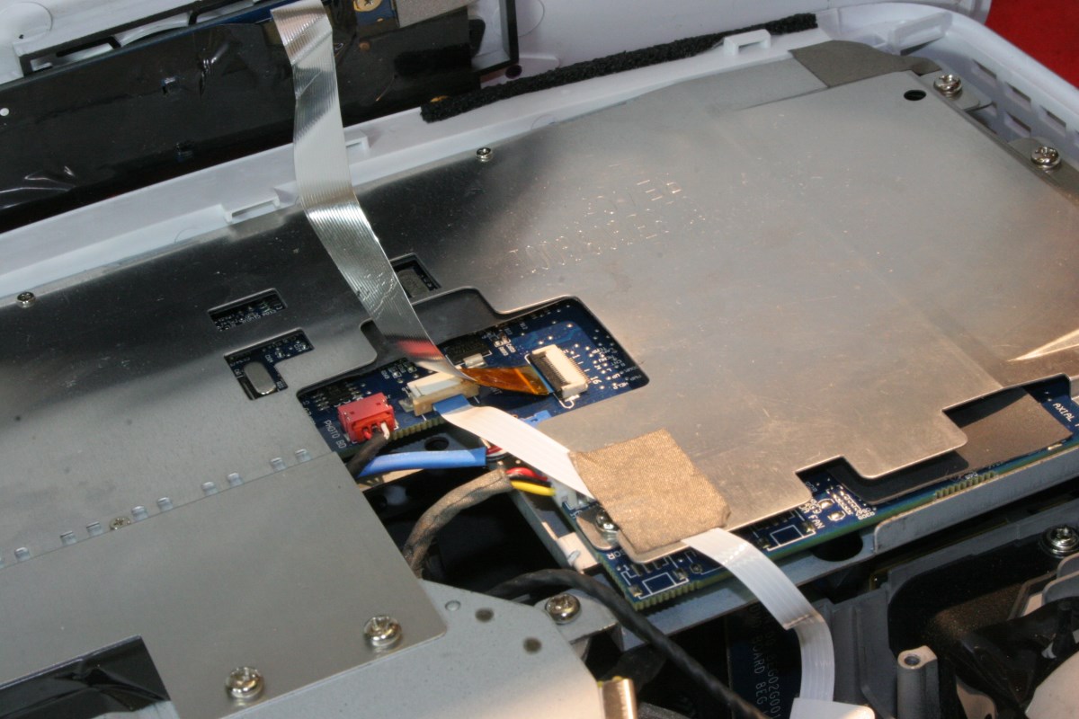
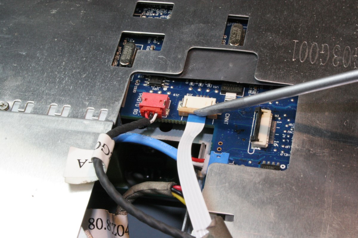
With the lamp removed, loosen and remove the only three recessed philips screws accessible from the bottom of the projector. Flip the projector back over to the upright position and carefully apply pressure to the sides of the case. Work the cover partially off by moving it forward and then STOP. A ribbon cable needs to be disconnected before the cover can be separated. Lift the black tab on the centrally located connector with a small screwdriver and the ribbon will release:
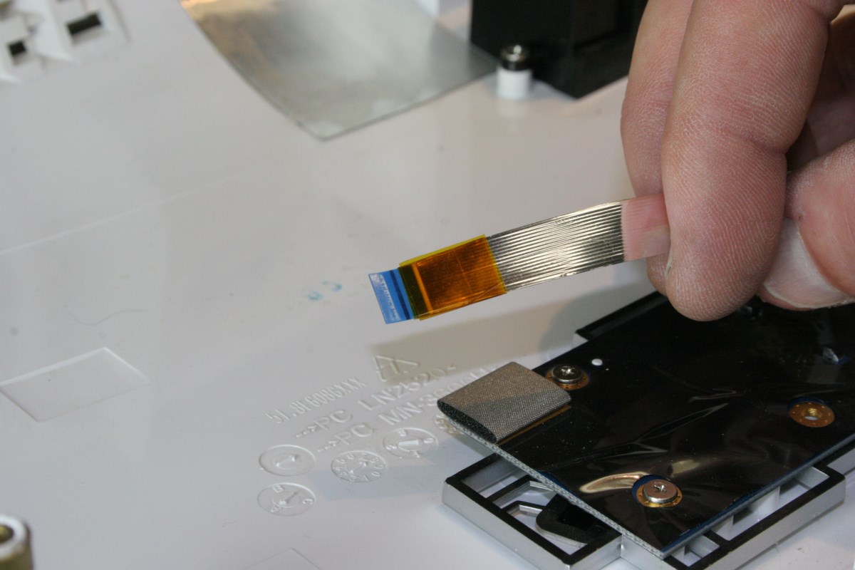
This would be a good time to look to see if your cable has a sharp bend at a weak spot near the end. If it does you can add a couple wraps of tape around the area to stiffen the bend to help prevent it from cracking when you reinstall it.
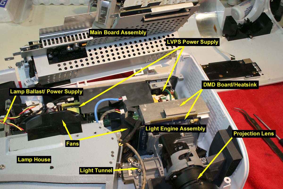
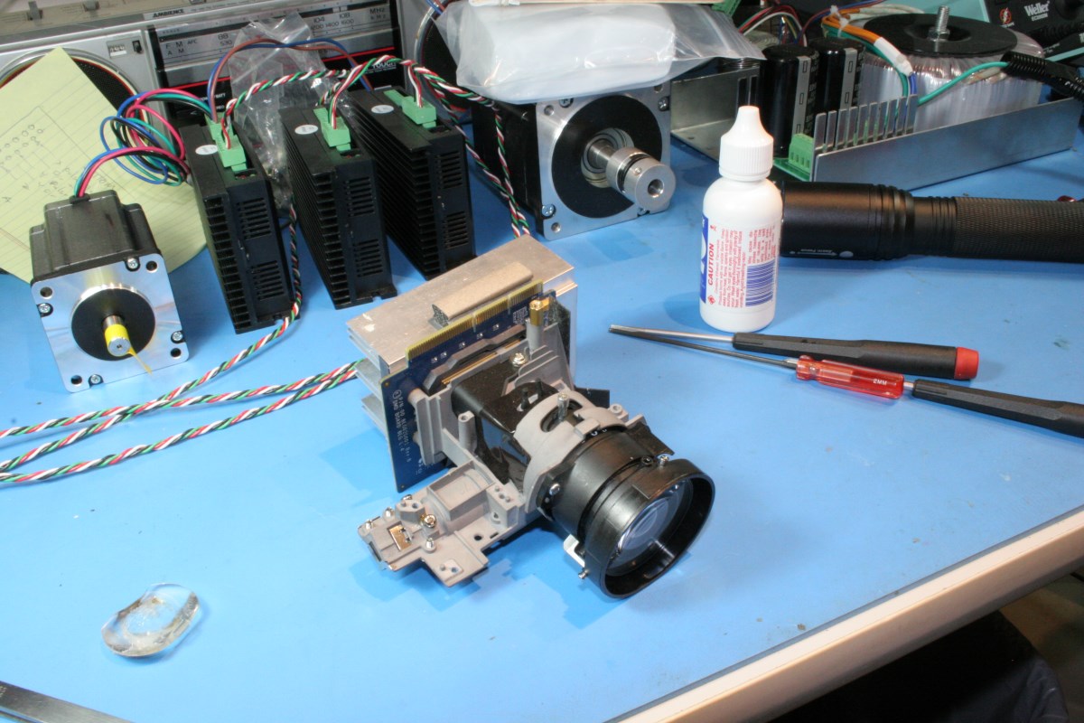
Here are some of the main sections of the projector that you can now or will eventually see with the cover and/or some components removed. NOTE: the color wheel has already been removed from the left end of the light tunnel and is not shown:
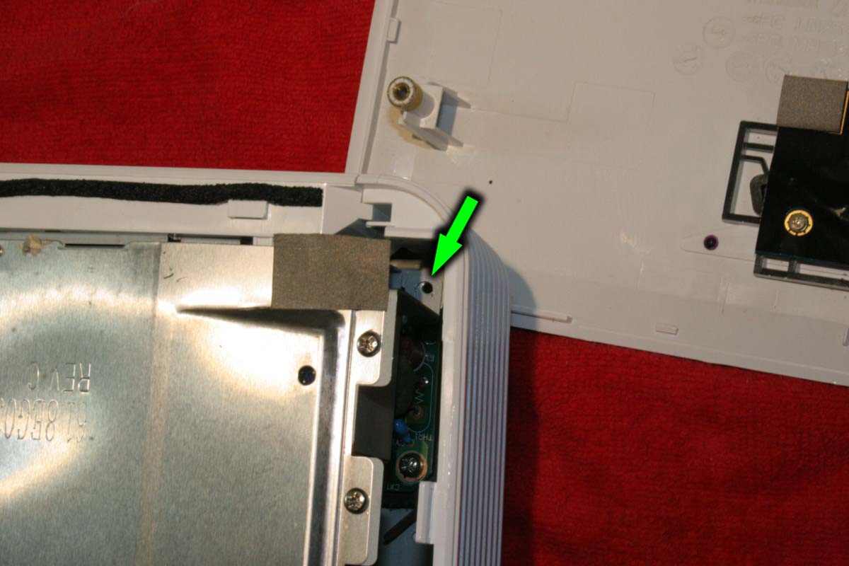
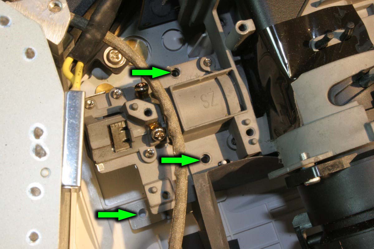
Set the cover aside and remove the screws shown at the arrows:

and this one on the right rear:
Next remove two color wheel leads shown below from their connectors. The left one just pulls out, and the right one needs to have the tan retainer pulled a little forward to release the flat ribbon.
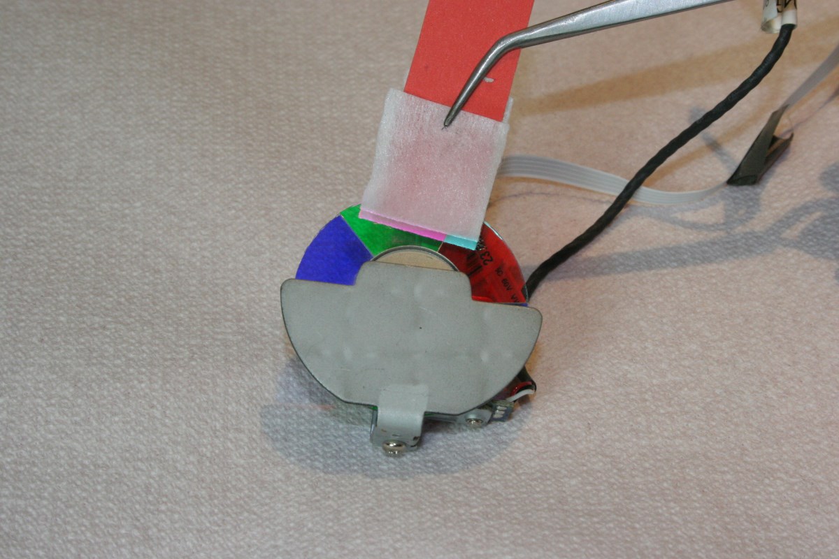
It is recommended at this point that you remove the color wheel. It can be removed later along with the light engine but it is such a delicate part that it deserves special attention. You have just removed the color wheel cables. Without bumping or touching the dichroic color segments on the wheel, remove the two screws show below:

Again without touching the wheel, lift the wheel and bracket assembly off the light engine while making certain that nothing gets bumped on the way out. Before putting the wheel assembly in a safe place (like a little box of its own) take a moment to inspect it for dust or film on the glass segments. If it needs cleaning, do it later. The wheel shown below is quite dirty, which will decrease light transmission to the DMD chip and eventually to the screen:

With the color wheel removed and in a safe place, remove these two cables:
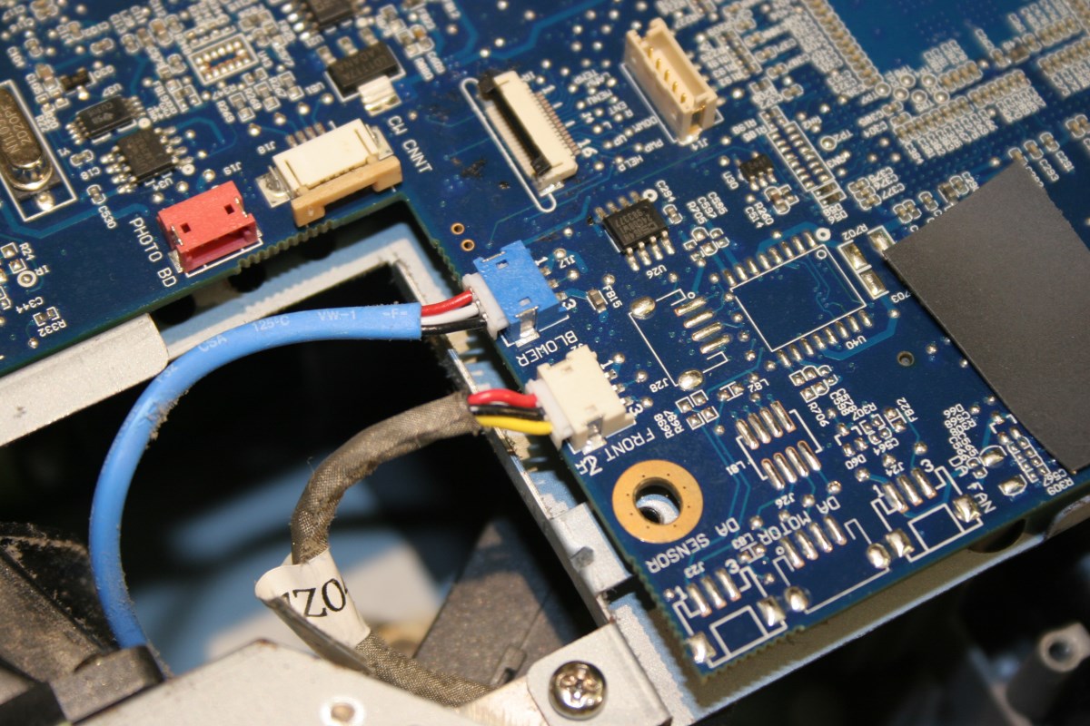
and these two on the left. The black cable connecter has a tab that needs to be depressed as it is pulled:

There is an edge connector on the blue main board at the front (above the light engine) that unplugs as you lift the board, and once this is clear the board assembly can be lifted up and swung out of the way. NOTE: the plastic back panel with all of the connectors is part of this board assembly and removes along with it.
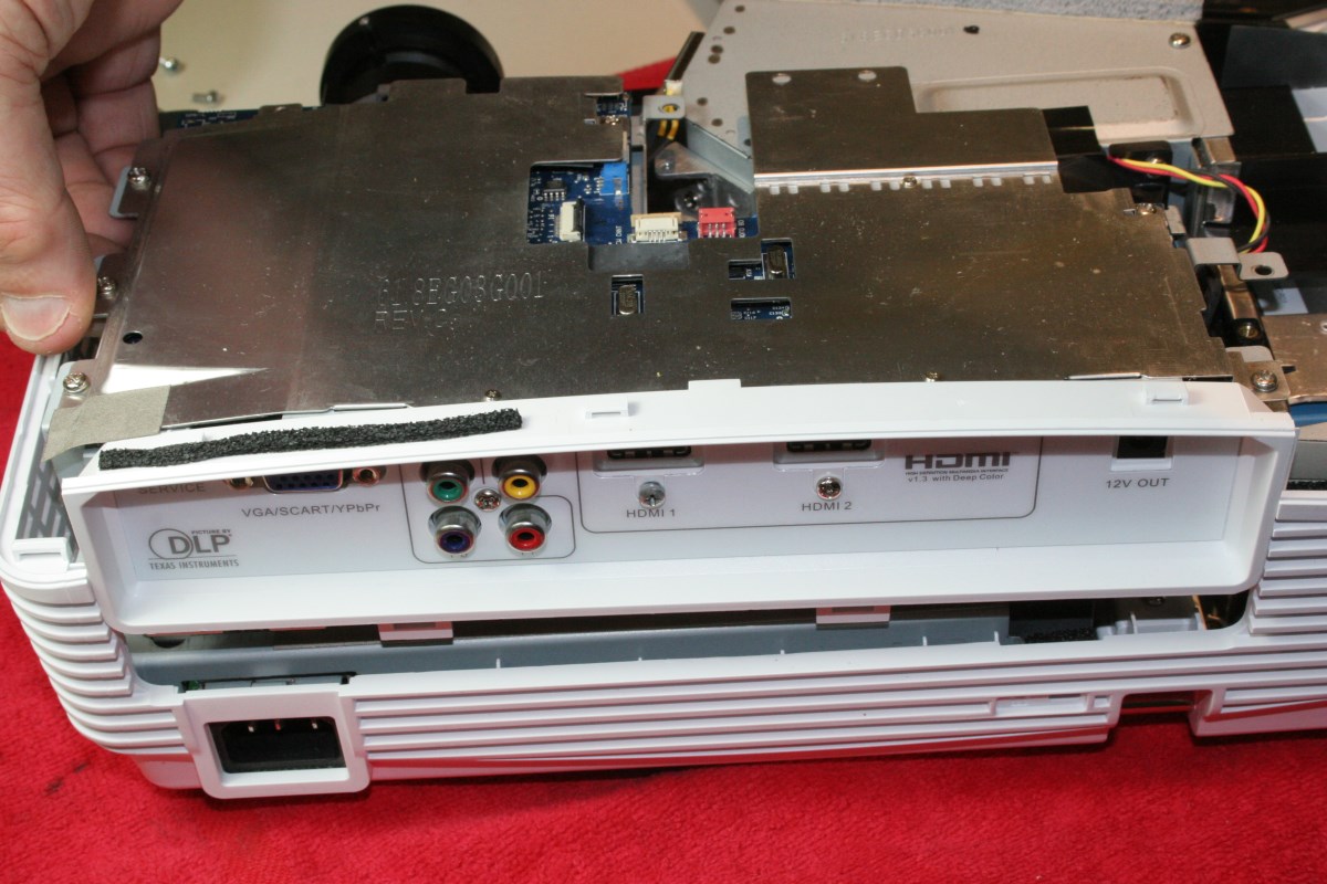
The Back Panel With Connectors Removes With the Main Board Assembly
There is still a large black cable connected to it which you can leave connected or remove to get the board completely out of the way.
The main board is now placed out of the way or detached to allow clear access to the light engine assembly:

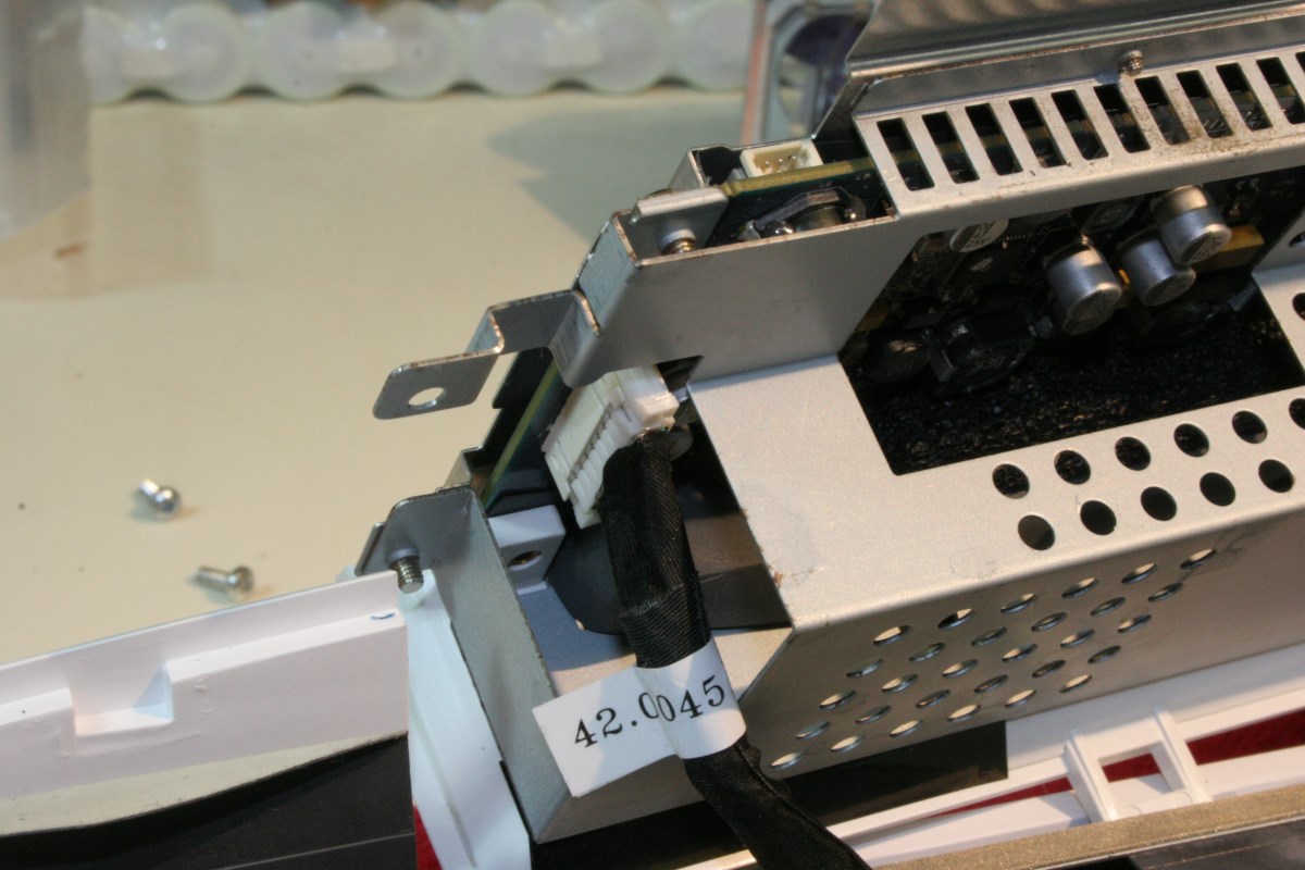
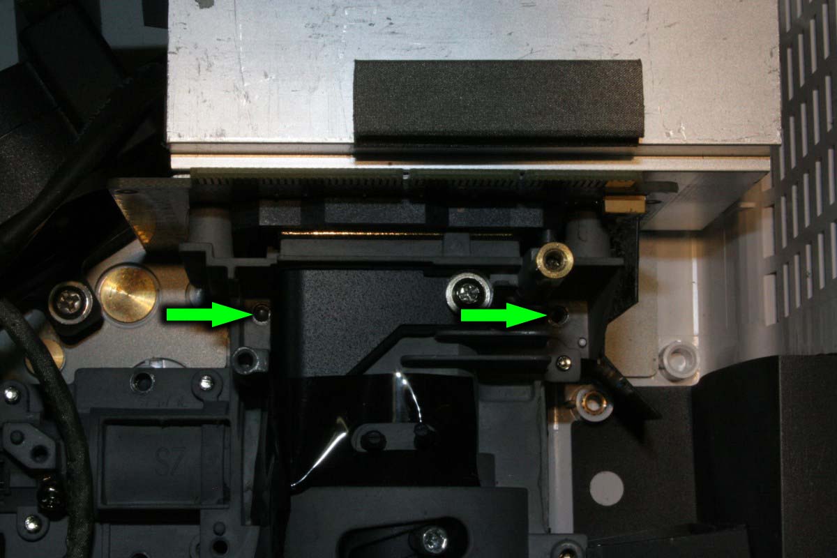
The light engine is held to the lower plastic shell by five screws – three near where the color wheel was mounted:
and two on either side in front of the blue DMD circuit board:
The light engine assembly with the attached heat sink can now be lifted out of the bottom shell. For working on the optics clear an area with some padding in case lenses should fall out, and if possible use an anti-static mat to prevent ESD damage to the exposed edge connector of the DMD board.
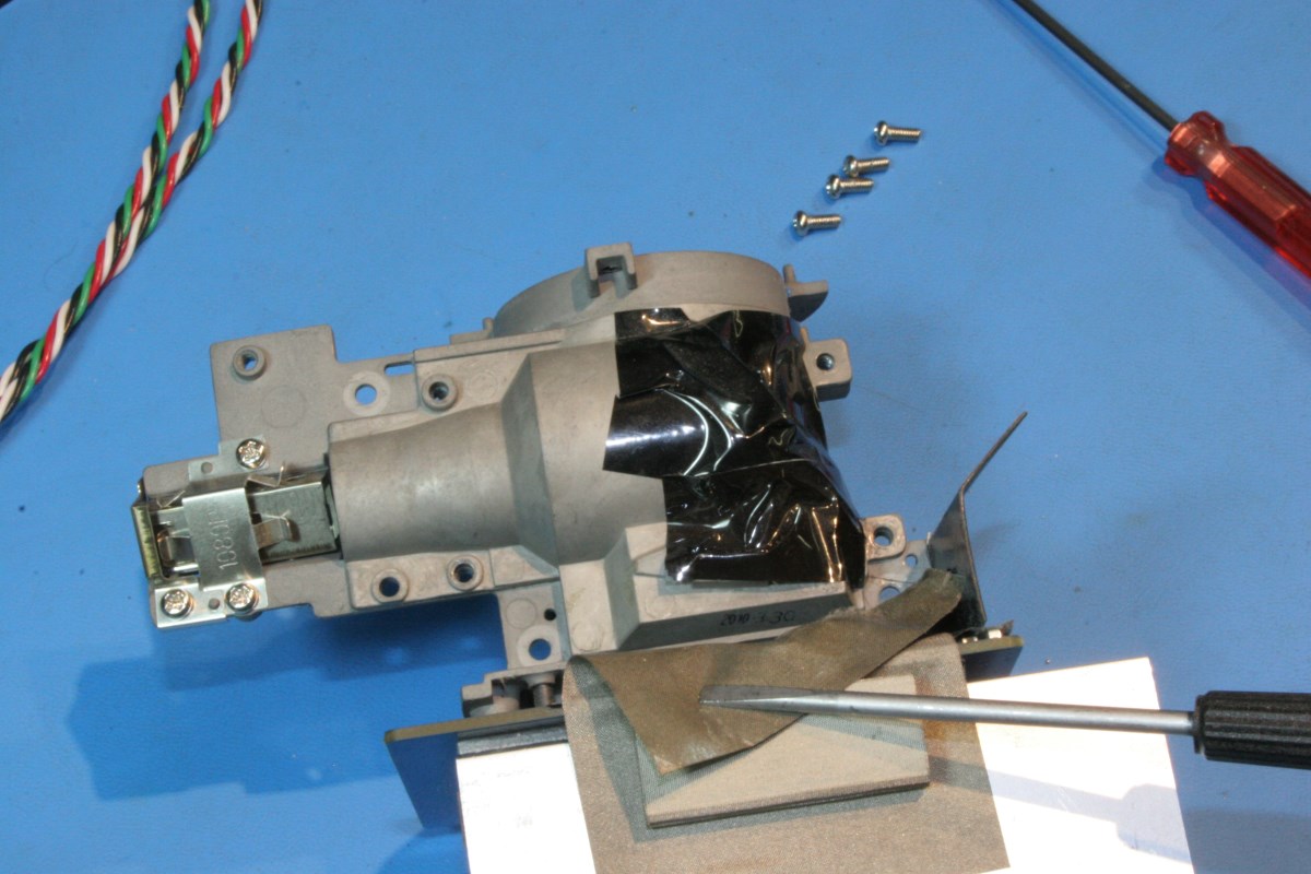
Here I have moved to my electronics bench with a mat and better lighting. Remove four screws from the metal cover that is partially covered in black film. Peel back enough of the silver EMI shield fabric to allow the cover to be removed, but STOP until you read the next step:
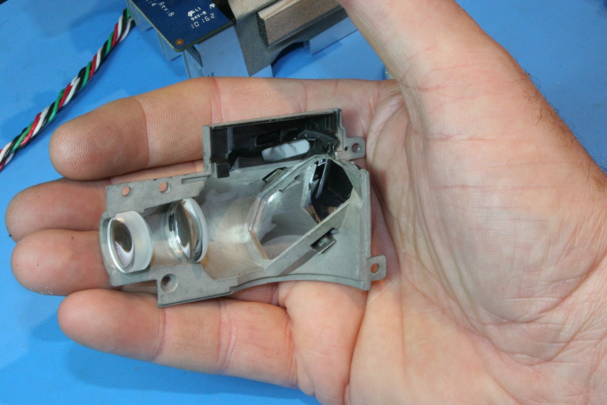
There are three lenses held in place by the lower cover, which is actually on top in the picture above. It may be safer to work with the light engine in the normal upright position, opposite to that shown here, with the removable cover on the bottom. There are two convex collimating lenses that are held to the lower cover with little sticky pads and they tend to stay with it, but be prepared for parts to fall out. Take a look at this picture before you remove the cover – in my case the smaller lenses stayed in the cover itself and the burnt lens remained in the main casting:

If the two lenses in the picture above should get loose, remember this: The thicker lens is on the left, and on both lenses the flatter side of the lens is facing left and the more convex side faces right.
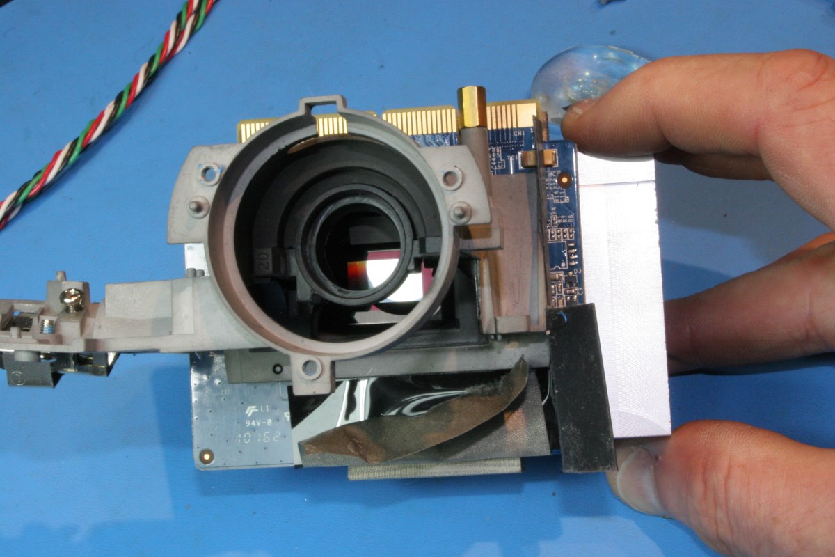
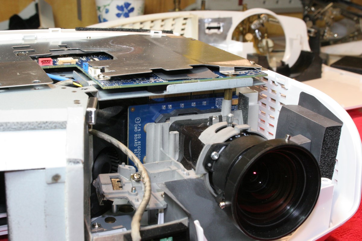
Here is another view of the interior:
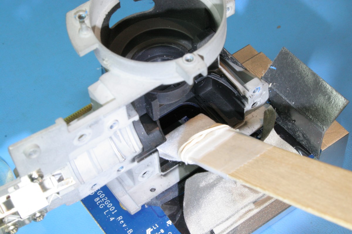
The burnt lens with a temporary repair is shown in position here because I needed to get enough light to the DMD chip to assess its health before I ordered the new lens. This procedure is actually documenting the replacement of the temporary lens. Note the odd angle angle at which the lens mounts:
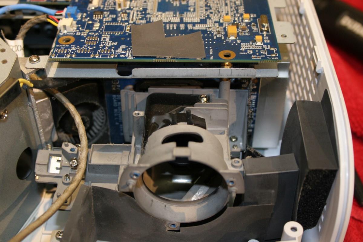
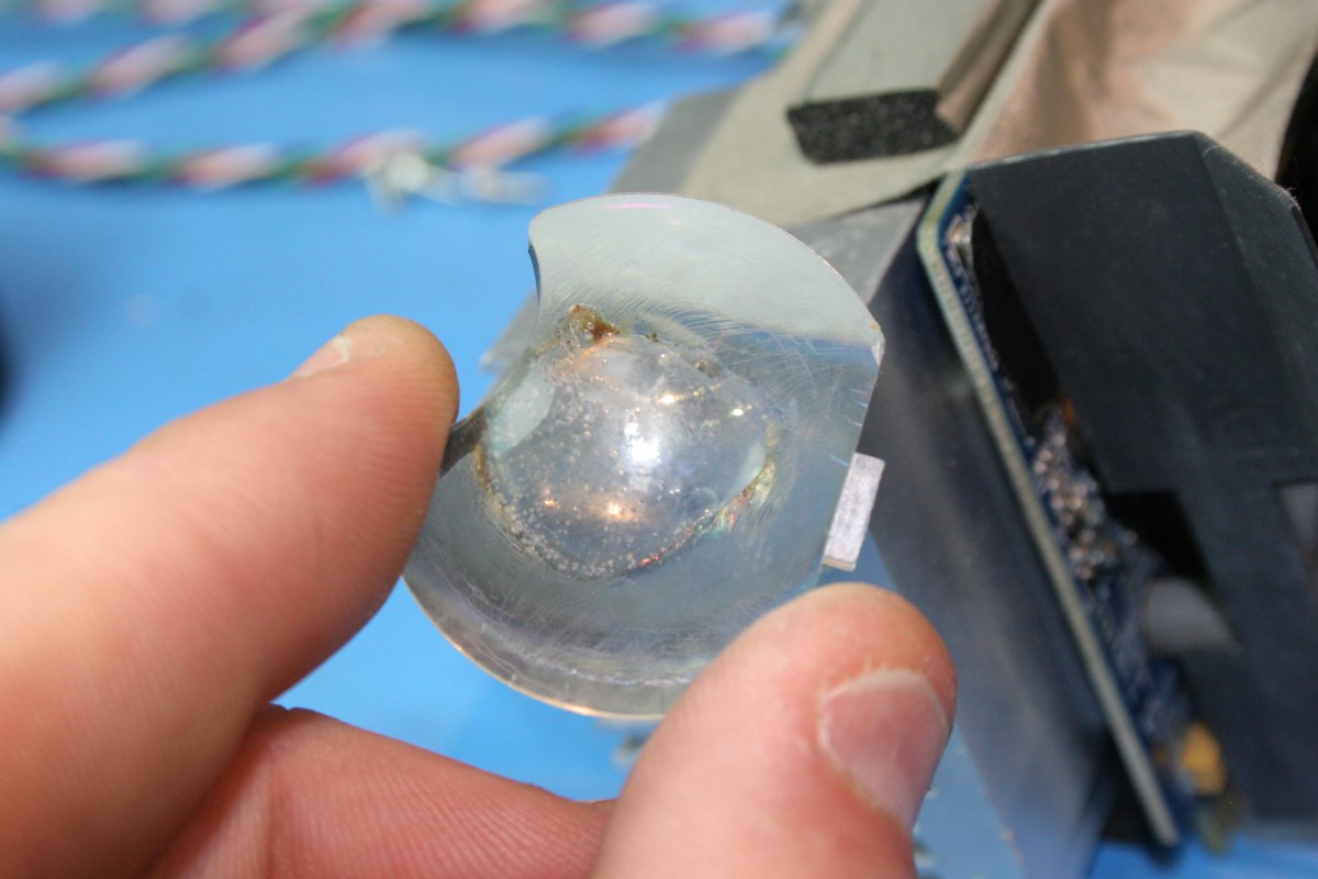
Lift the damaged lens out of its niche and you will get a clear view of the mirror-like DMD chip:
At this point some cleanup is generally required. One byproduct of the lens meltdown is that all optics and even the plastics exposed to the melting lens may be covered in a hazy film or even some sputtered plastic nubs. Use a bright LED flashlight to inspect the surfaces of the smaller lenses, the front surface mirror, and finally the face of the DMD chip itself. My projector had a hazy film on everything, and some surfaces even had a sticky greenish yellow film on them. The front surface mirror is located near the burnt lens and had a few hard spots of melted plastic that I just left – I believe the mirror is not at any focal plane, so the spots do not appear on the image; they simply contribute to a very small percentage of light loss.
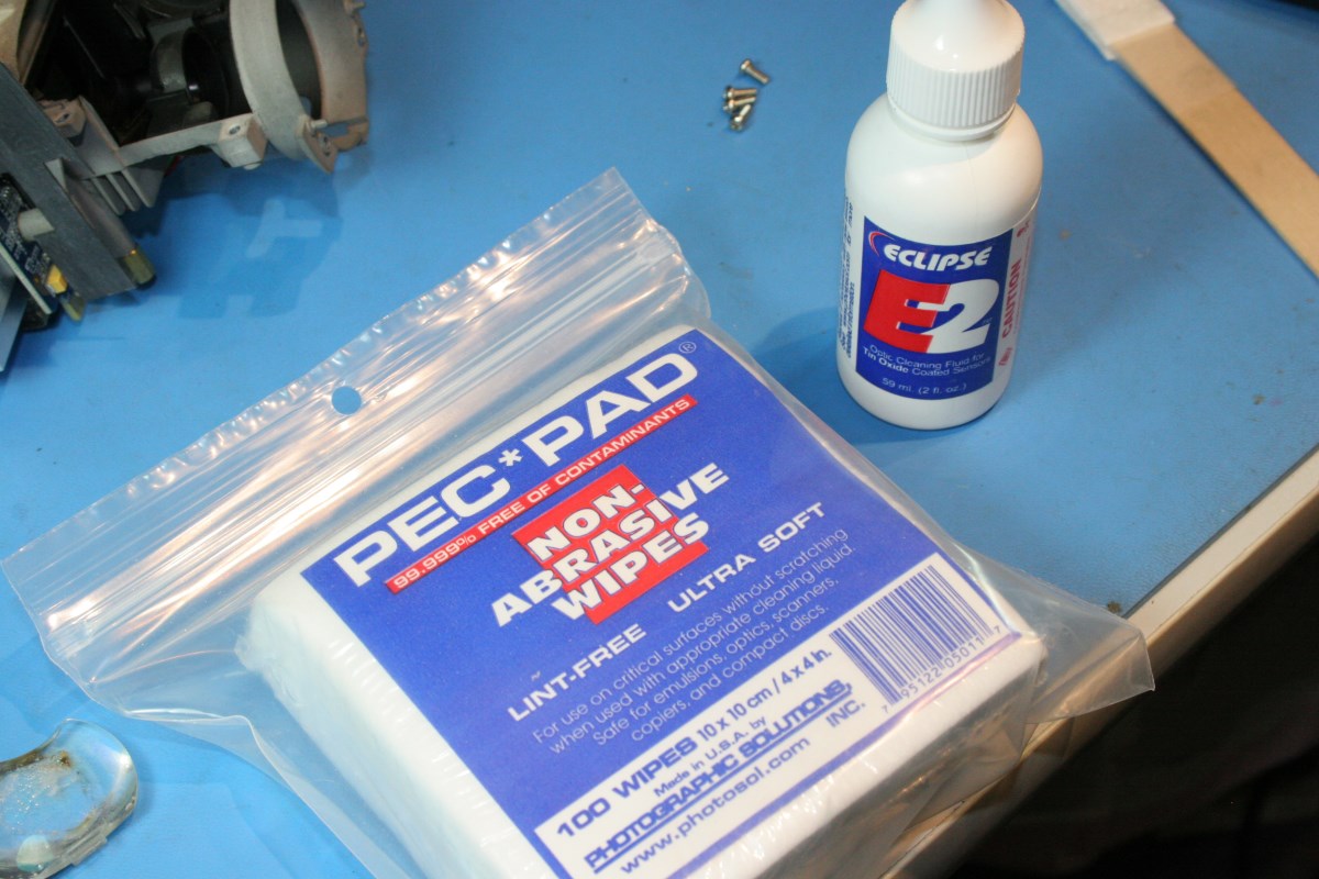
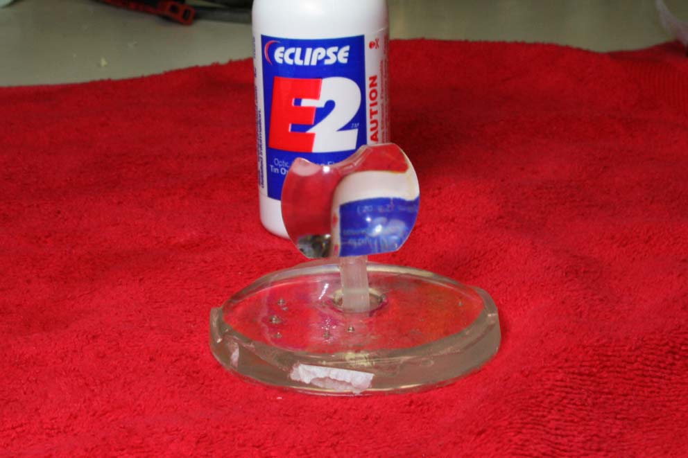
All of the optics in these photos were cleaned previously when the temporary repair job was performed on the burnt lens, but I cleaned them again when the glass replacement lens was installed. I used the nearly the same process that is used to clean digital camera sensors to clean the DMD chip, the mirror, and the color wheel. I used Pec Pad wipes and Eclipse fluid:
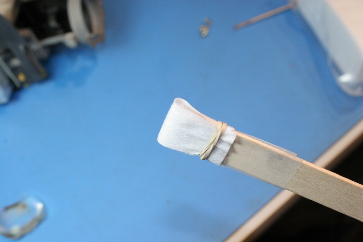
Pec Pads do not leave any dust but they do occasionally leave fiber strands that need to be retrieved, so have tweezers at hand. For a flat swab I used a tongue depressor with one end cut off square. Over this I taped a strip of a soft paper towel to add a little resiliency and extra absorbancy. DO NOT use this just yet.
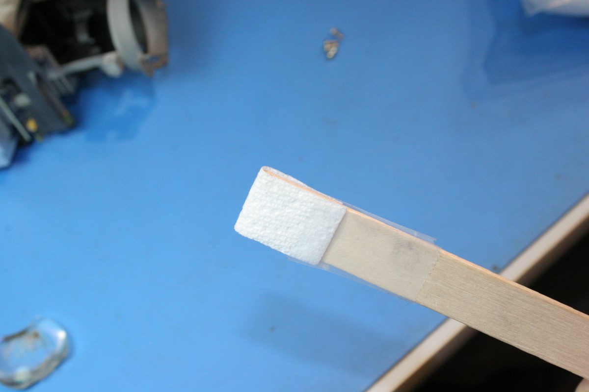
On top of the strip of paper towel I added a slightly wider strip of Pec Pad and held it on with a rubber band so that it could be shifted to present new clean surfaces.
The surface of the DMD chip was cleaned of film by adding a few drops of fluid to the swab and making a series of single strokes from the top to the bottom of the chip. The swab was flipped over to present a new clean edge and the chip stroked again. The Pec Pad was then shifted slightly and the steps repeated until no haze or film was left on the DMD chip surface. Every stroke of the swab used a new clean portion of Pec Pad, and the fluid was added as necessary to keep it slightly moist.
The same process was used for cleaning the mirror:
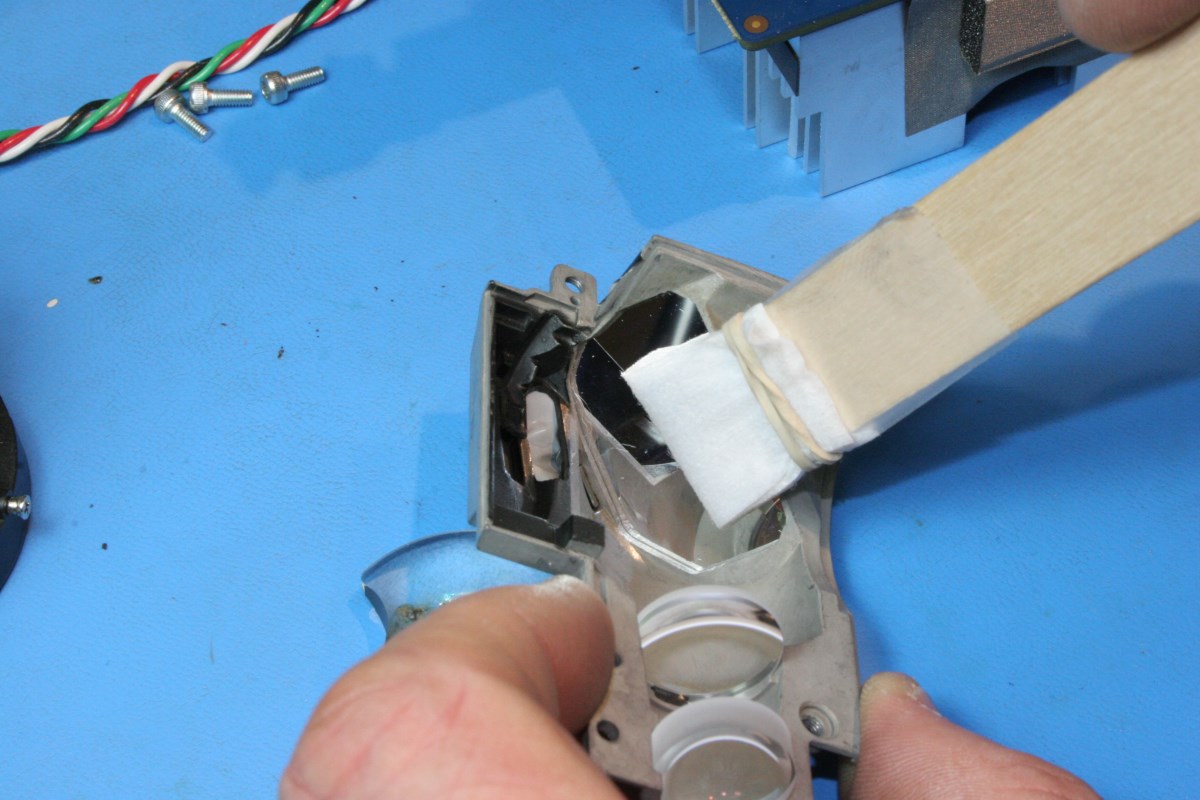
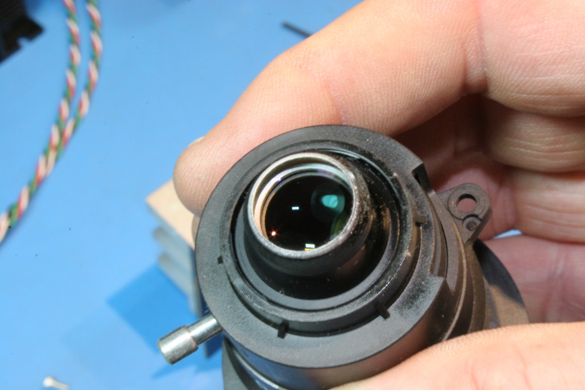
The two smaller lenses in the foreground of the above picture were removed and gently rubbed with a microfiber cloth wetted with a few drops of the fluid. The inside of the projection lens was also covered in a film, and this shows the lens after cleaning:
Cleaning the color wheel was the most delicate operation. The wood tongue depressor swab was too stiff, so a strip of a business card was used with a single strip of Pec Pad over it and held in tweezers. The pad was kept quite moist and stroked outward across the glass segments, and it was changed frequently. There was no rubbing and the pressure was very light. It actually took some time to get all of the surfaces clean.
If you have any other film or sticky residue on plastic or metal in the area of the lens it can be cleaned up with alcohol and some cotton swabs.
The light engine can now be reassembled with the new lens.
NOTE: Before any access to the DMD chip is closed up, make sure that the surface is free of any dust specks or fibers. Anything on the surface of the chip is very likely to block pixels and show up as dark specks on the projected image. This is the most important area to keep clean – specks of dust on other optics are more tolerable but the DMD chip must be clear. Use a very bright light from different angles to illuminate the surface, and use canned air or a soft artist’s brush to chase any specks away.
The semi-circular cutout in the lens makes the orientation obvious. Clean the lens with microfiber cloth if necessary and place it in the pocket of the light engine casting or the bottom shell depending on how you want to assemble the parts:

The New Lens is Placed in Position
Mate the bottom shell with the two small lenses (in the correct orientation) to the bottom of the light engine casting. Insert the four screws and press the metal EMI tape back in place. My tape had lost its stickiness, so I sprayed a little 3M 90 spray adhesive in a cup and dabbed in on a few key spots before pressing it in place. I did not fully coat the tape because the original adhesive may have been conductive and if so the EMI effectiveness would be impaired with a thick insulating adhesive. I used just enough to hold the edges down.
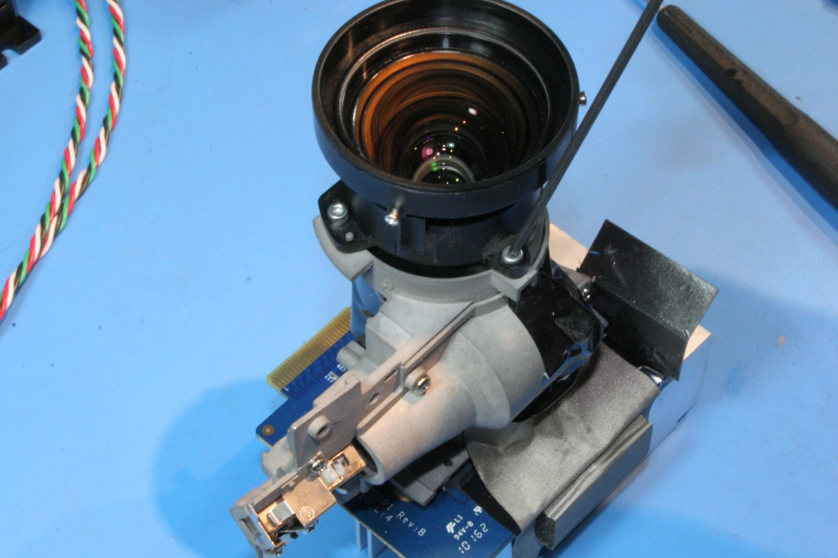
Reinstall the front projection lens using the three socket head screws. Here is the repaired light engine ready to go:
This would be an opportune time to perform some routine maintenance on the rest of the components while the projector is apart. Fan inspection and dust removal is the priority.
Take a close look at the two fans that force air through the lamp house. Make sure that they spin freely and if the impellers are loaded with dust, blow them out. If the dust doesn’t blow out easily it’s a good idea to take the time to clean them thoroughly with alcohol and cotton swabs. The fine impeller blades of the smaller pressure blower are tedious to clean but both of these fans are important for prolonging the life of the lamp and the electronics.
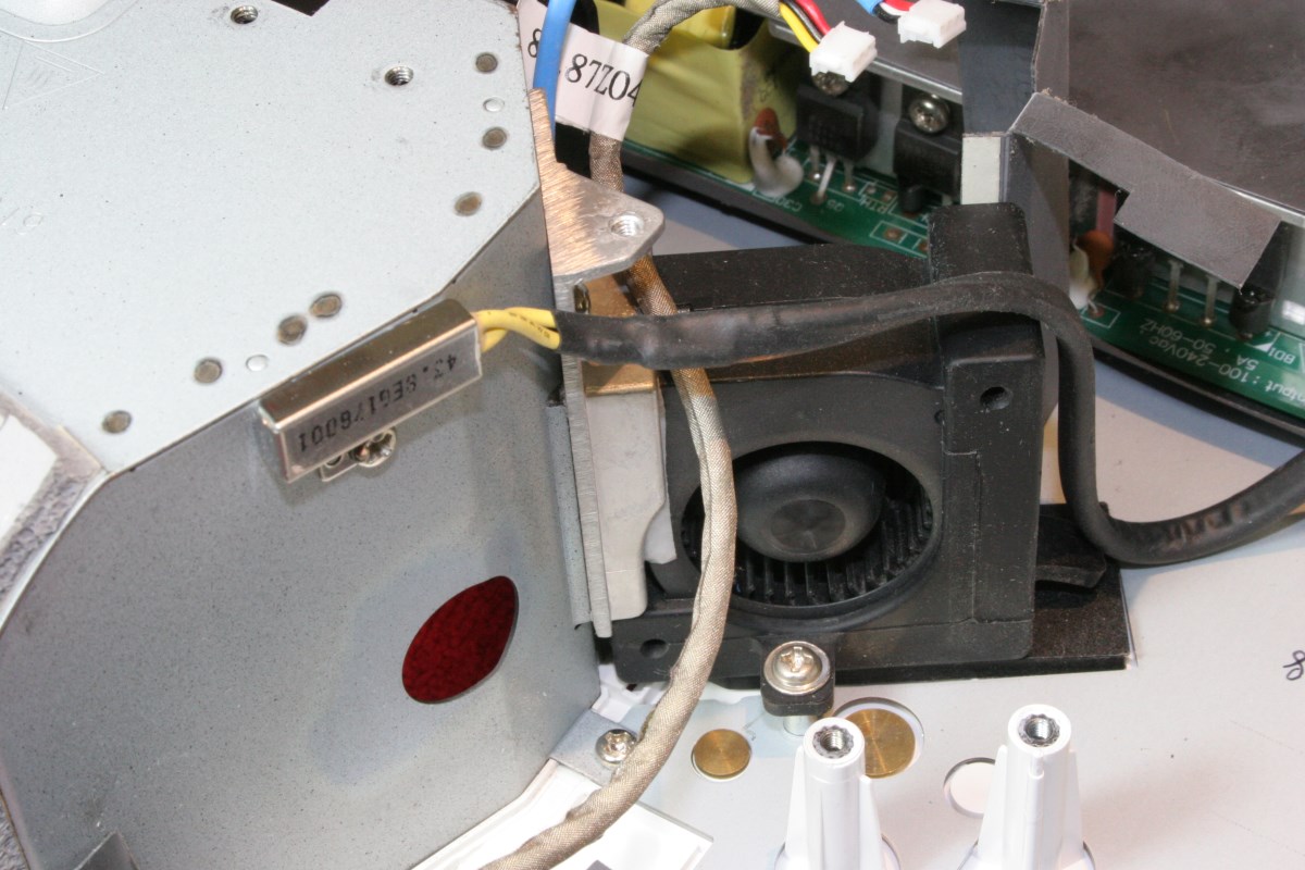
Lamp House Pressure Blower
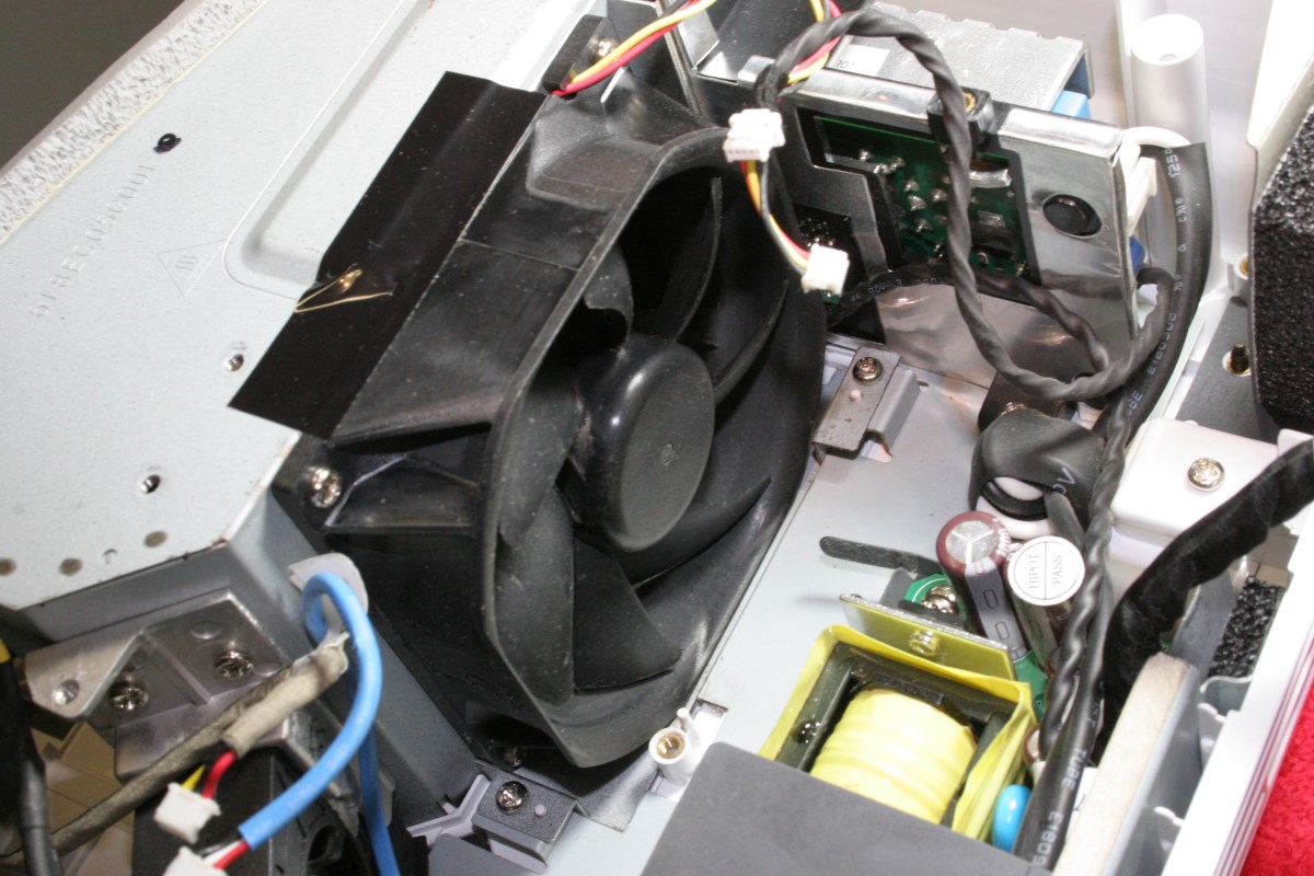
Fan Located at Rear of Lamp Compartment
Check for dust encased parts, particularly heat sinks, on the lamp power supply (to the side of the lamp compartment) and the LVPS module across the rear of the case. Use compressed air to blow any dust film off the components.
Apparently someone had been inside the case of my projector before because I found several of the threaded posts in the plastic case to be split. In a couple of cases a threaded brass insert in the end of a plastic boss would spin so that it was not possible to tighten a screw. I went around and used a little cyanoacrylate adhesive (CA, a.k.a. superglue) to lock these inserts, using care that none dripped into the threads. In one case the plastic boss was split so badly that I had to find a small brass sleeve to shore it up.
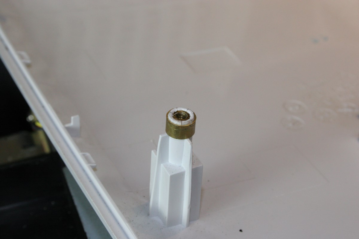
Brass Ring Reinforces Split Boss
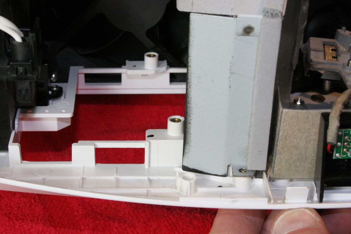
Both of These Lamp Module Threaded Inserts Would Spin – A Spot of CA Fixed Them
Reinstall the light engine in the lower plastic case (5 screws)
Next reinstall the main board assembly by first inserting the plastic backpanel into the rear slots in the lower case. Make sure that the larger black cable on the bottom left side of the main board is attached if you removed it earlier. Keep the board assembly flat as you lower it until the right front board connector comes down on the vertical blue circuit board on the light engine:
Ease the Main Board Down Onto the Light Engine Edge Connector
Now press the board connector onto the light engine contacts until the gold contacts are no longer visible from underneath:
No Gold Contacts are Visible When the Connector is Fully Seated
Reinstall the screws that were removed previously from the main board assembly. I think on my unit there were three different types of screws: the coarse thread went into plastic, the medium pitch thread was for the sheet metal holes, and a fine thread screw went into a brass bushing on the top right of the light engine.
Reinsert these cables:
and then these:
Reinstalling the color wheel has been left until near the end. Retrieve the assembly form the safe storage location where you hid it earlier. Carefully insert in onto the mounting pads on the left end of the light tunnel. Adjacent to the two mounting screw holes are two smaller holes for alignment with pins on the light tunnel. Do not use any undue pressure when seating the brackets onto the alignment pins.
Before inserting the screws make certain that a gap is present between the glass wheel segments and the left end of the light tunnel and that the brackets appear to be seated corrected. Reinstall the screws:

Make Sure You Have This Gap and Watch it as You Insert the Screws
Reconnect the cables from the color wheel to the main board and stick the EMI tape on the ribbon cable back onto the top sheet metal shield:
Insert the Ribbon Cable Fully Then Slide The Tan Retainer Into the Connector
At this time you can recheck all connections, reinstall the lamp module, and test the projector out using your remote control. You may want to perform an additional procedure that adjusts minor misalignments in the rectangular light pipe (they call it the “rod”) in the light tunnel to optimize the illumination and uniformity across the screen. You should refer to a service manual for that procedure. To their credit, OptomaUSA makes the service manual available for free here.
When you are finished you can reinstall the keypad ribbon cable to the connector in the center of the main board. Make sure that the zoom pin on the projection lens is pointed straight up, and turn the zoom knob on the cover so that it engages correctly with this pin as you snap the lid into place. Install the bottom screws and the lamp module cover, snap the focus bezel in place and you should be good to go.
Lens Hack: A No-Cost Lens Repair
Let’s say you’re not too worried about color or brightness uniformity on your projector, but you want an image back without spending any money. This crude repair of the lens was remarkably effective at making the projector functional again. Remember that this is not a telescope lens; it is used for light collimation and only affects illumination.
I did this out of necessity because I want to check the condition of the DMD chip before I put any money into a new lamp or replacement lens. If I had dead pixels I wouldn’t bother repairing the projector.
Knowing that the burnt lens was fairly non-critical as optics go, I used a ball-end burr in my Dremel tool to carve the burnt material out of the plastic lens like I was doing some large-scale home dentistry. Once I carved all of the black and brown melted material out I kept going until I removed most of the bubbles deep in the lens. There were still more bubbles, but I couldn’t go all the way through the lens.
When I had the cavity drilled out so that only clear plastic remained, I positioned the lens on a ball of clay so that the top of the cavity could be adjusted to be approximately level, and I filled it with clear epoxy, and let it cure in a pressure chamber (not essential). If you don’t have a vacuum/pressure chamber to eliminate bubbles try to pick a slow cure epoxy or one of the clear craft embedding resins that take 12 to 24 hours to cure. Polyesters may cure too quickly. But this is a crude repair and the only latitude you have is in the degree of crudeness.
Carve Out the Burnt and Bubbled Material With a Dremel Tool…
Then Fill the Cavity With Clear Epoxy
I could anticipate all of the things wrong with doing this: epoxy has the wrong index of refraction and poor clarity, not to mention the effect of having a flat spot on the lens where the epoxy leveled.
But guess what? It worked amazing well. Yes, white uniformity was crap and there was some coloration at the corners, but I was able to completely check out the health of the pixels and projector operation. And while I was at it, I watched half of Avatar hardly noticing the aberrations. So if you only use your projector for PowerPoint presentations or retro games, it’s an option, even if it is worthy of appearing on There I Fixed It.
Some Final Thoughts
If you should replace your lens with another plastic one, consider checking your projector settings to maximize cooling. You can choose to run the lamp in economy mode (SYSTEM > BRIGHT MODE > OFF) which will slightly reduce the brightness but significantly extend lamp life and possibly reduce the chance of cooking the new lens. Another option that is beneficial to the electronics in general is to run the cooling fans at high speed (SETUP > HIGH ALTITUDE > ON).
On the subject of scratched lenses for this application, I did say that the light collimation path is more tolerant of dust and defects than the image optical path would be. The problem with too many scratches and surface flaws or films is that the light that hits the DMD chip is not only slightly reduced, but it is diffused, with stray light illuminating areas around the chip. A sharp rectangle of focused light projected onto the DMD chip from a clean set of light tunnel optics becomes a bright rectangle with a cloud around it when the optics are scratched and are scattering light. Why does this matter? Because stray light falling even on the black internal surfaces of the light engine housing around the DMD chip contributes to light bleed and consequently a loss of contrast. Don’t accept a scratched lens if you are told it doesn’t affect performance, because it does.
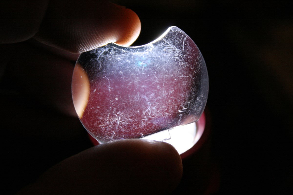
At least I know I’ll never need to buy another lens. How do I know? Because before I installed my lens I made a silicone mold of it, and now I can grow my own for about 50 cents using water-clear urethane resin, which has a nearly ideal index of refraction. Here’s a test sample (cast in a yellowish urethane resin):
![]()